Here is a quick post with the (re)construction of Chibi in pictures.
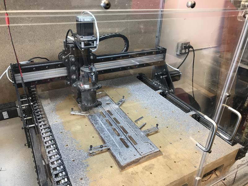
This is Chibi Mk II. This was based on the original design of Kuro and was driven by 20mm HTD-3M belts. It used open v-rail and and a harbor freight trim router for the spindle. It was a good design, but as you can see by what I was cutting (the x rails for my Oddbot), I was pushing the limits of what can be done with a belt driven machine and delrin wheels. While it worked well, it still didn’t have the repeatability, accuracy, or strength that I really needed.
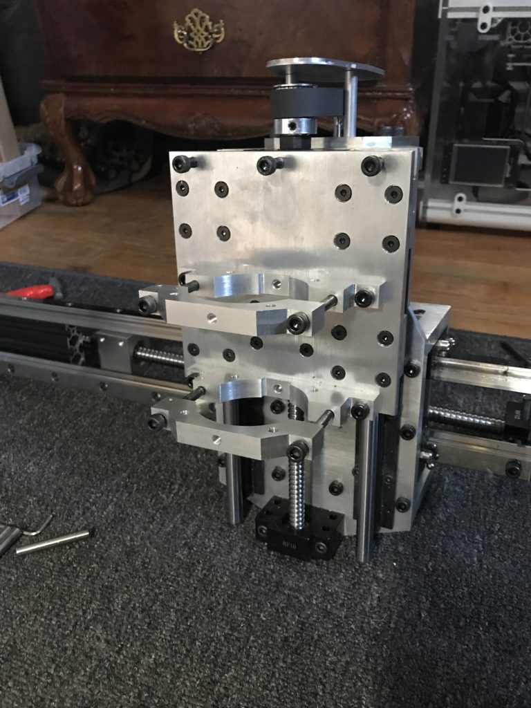
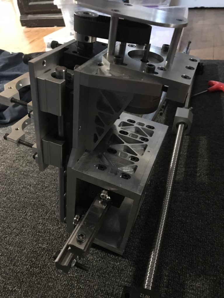
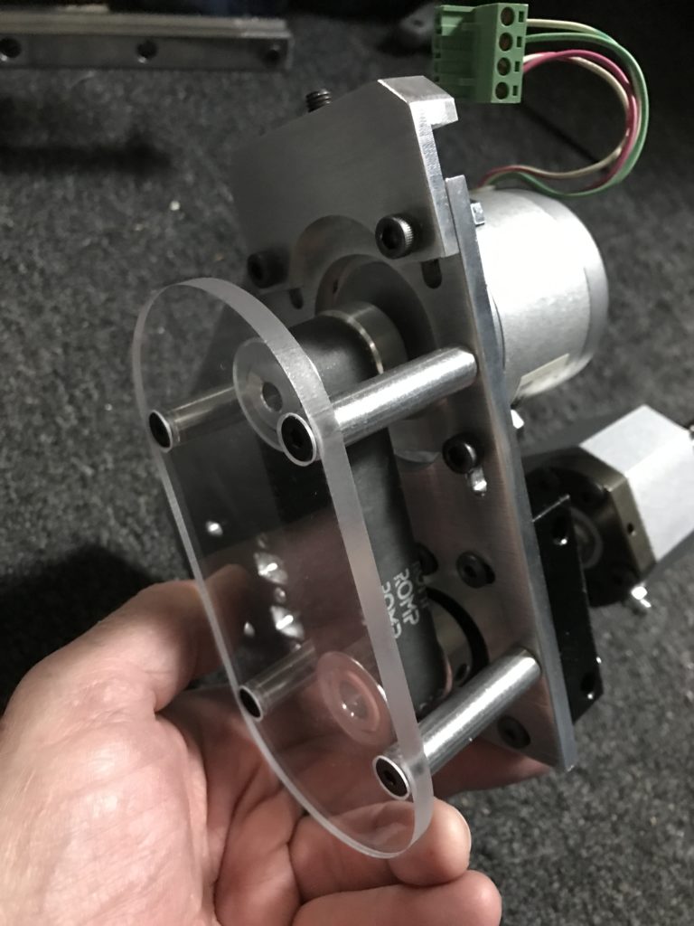
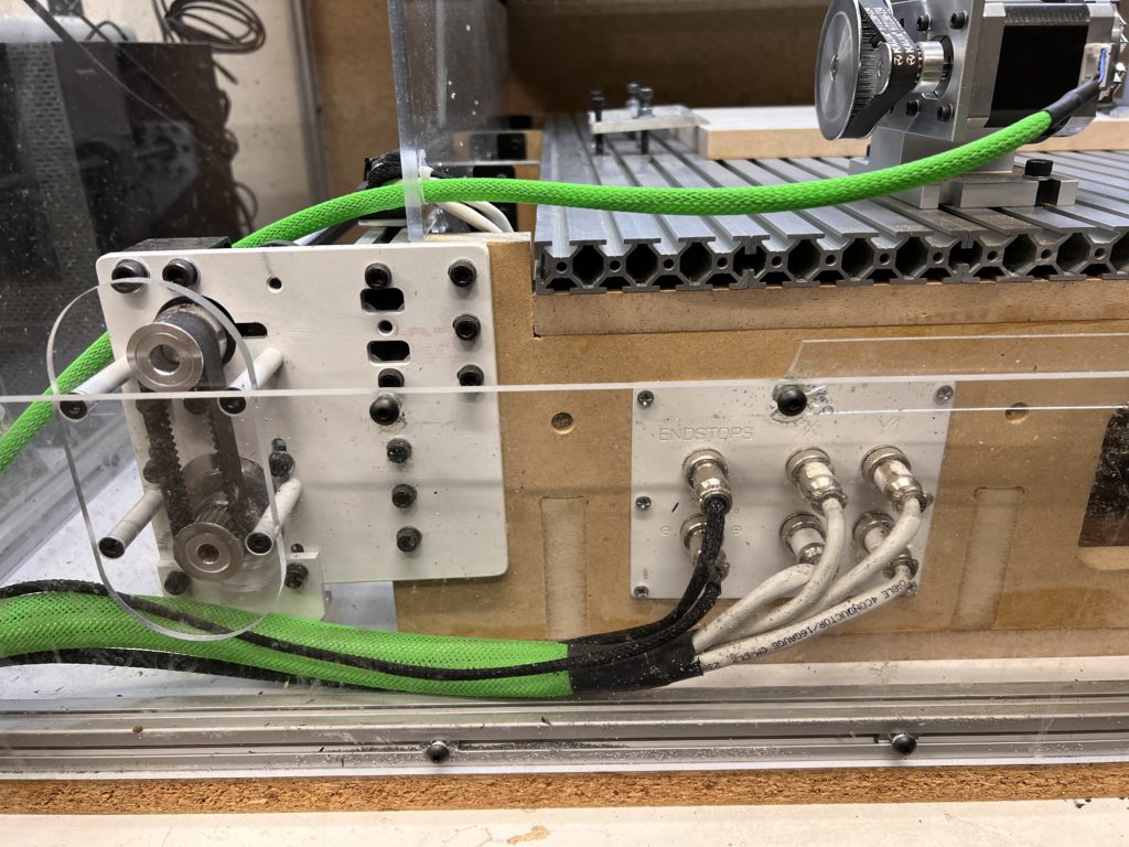
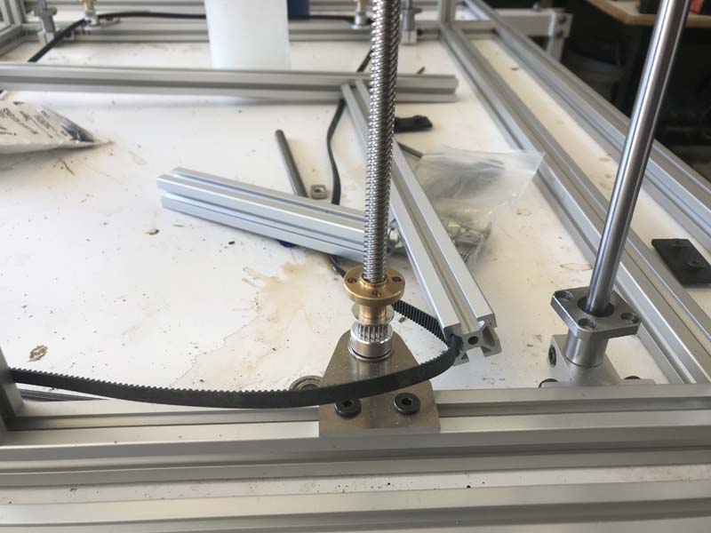
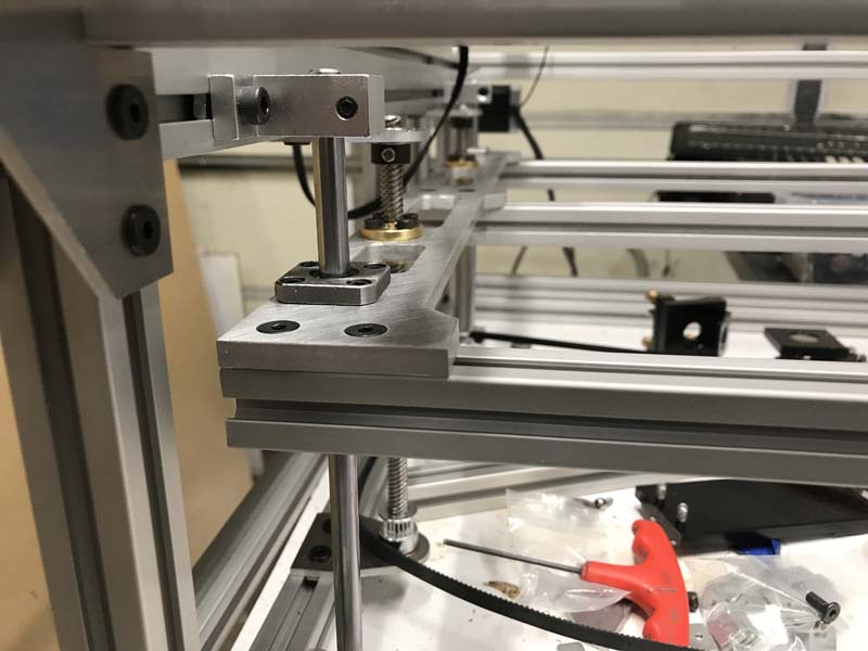
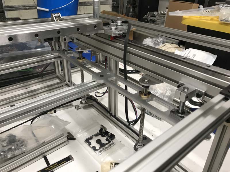
Chibi II after a spindle upgradeThis was the first assemly of the X axis testing to see if all the parts fit correctlyThe back side of the X axis. Note the belt tensioner above the motorOne of the Y axes being test fit with a dummy motor on itAfter the powder coat and beginning assembly. This is when the wiring was just beginningInstalling the debris shieldsOne of the Y axes with connectors and 4th axisAnd the completed Chibi III
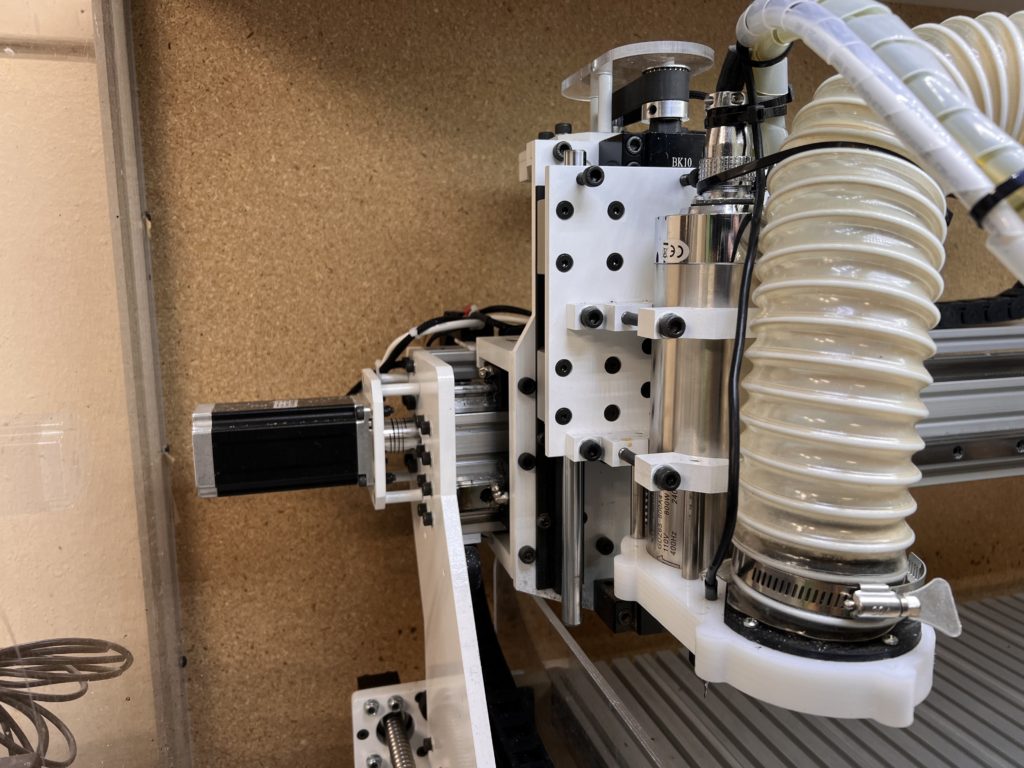
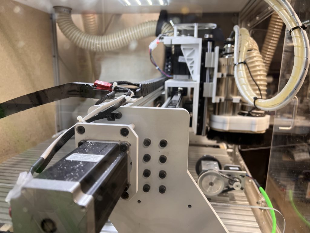
The final completed Chibi Mk III is built entirely out of 10mm and 12mm aluminum plate. The ballscrews are sfu1605 on the X and Y, and sfu1205 on the Z. The linear guides are trh20 and there are 2 on the X and 1 on ech side of the Y. This is not a fast setup, but it is extremely strong and very accurate. It is nice to work on a long cut and not have to be paranoid of a belt breaking in the middle of it!
It is set up in linuxCnc as a XYYZ gantry. For the controller I went with a Mesa 7i96 ethernet board. These little boards are so awesome! You don’t have to worry about using a realtime kernel and all the other headaches of a parallel port. They can be configured as 5 stepgens or 4 stepgen and 1 PWM. Before I went to 4 axis, I was using the PWM port to control my spindle vfd, but then I needed it to run the A axis, so I used the built in RS485 controller with a usb to RS485 adaptor for LinuxCNC.
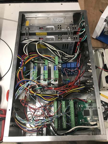
Controller box in all its rats nested glory
In the future though, I do believe I will redo the controller box. One thing that I want to do is power each driver on a separate power supply. Right now I am running it at 48v with 4 Stepper Online DM542Y stepper drivers and 2x 48v 7.3a power supplies. The nice thing about them are that they have active cooling and are super slim vs typical switching power supply. These were the first digital drivers that I tried and did not realize how much of a difference that they mad in performance! The original drivers were the Toshiba 6600 series and they got hot and lost steps. These are super quiet and powerful and I really love that they don’t shake the foundations with the hard startup!
It’s been a minute since the last post and of course when it rains, it pours. After a horrilbe bout of covid and my birthday curse terminating in the loss of a special friend, I really havent had the motivation to really do much or post anything. I was coming off the passing of my friend Damage and so this was a compounded loss…
I love and miss you Miss Honey my pretty girl!
The hardest part of covid I think wasn’t the actual illness, but the fact that it seems to steal a part of your soul. There is no other way to describe it except as a missing part of your being. I had the lack of energy and lethargy real bad, but it seemed more than that. It was as if somebody surgically removed my desires. I would get exhausted just going up and down stairs and doing simple things. That was a physical symptom and would anger me because I have never been weak like that before. But the missing soul part, that was extraordinary. I am only now just getting to where i can even go out to the shop after 2 months of doing my best imitation of a gelatinous growth. But now I am attempting to rekindle the fire that drove me so I will be posting a bit more in the future.
So after getting tired of trying to fasten parts down to the wasteboard and my wasteboard bowing, I finally decided to actually create a rail system for my bigger router. I had toyed with the idea for a while, but truthfully I have been lazy and not very motivated. Winter is a bad time of year for me and in the fall I begin to start feeling down and this year has been a rough one with the city waging war against me, having to move next year, and of course losing my best buddy Damage…
My buddy Damage and his favorite purple towel after bath time
So in order to get me up and moving, I have been giving myself projects that are not too difficult that I can complete with few if any problems to keep my frustration quotient low and keep me moving otherwise I might end up melting into whatever I am sitting on. As part of my continuing upgrade of my larger router, I decided to redo the deck and fastening system.
Now keep in mind that this is just a temporary upgrade because I have never been satisfied with this design and on the next iteration, not only will it be larger, I will be doing away with the v-wheels and the belt drive. Those are both good for low cost and simple machines, but some of the things that I have been doing are beginning to test the limits of both systems. I am not sure if I will be going to fully suported bearings or linear rail, but right now both are being considered. As for the belt drive, I am just beating a dead horse with that one. On the one hand, it is fast, but it is anything but accurate. I have to recalibrate it at least once a month.
So in the future, I am pretty decided that I will be going with a rack and pinion. For my purposes, it should run just as fast which considering that I am wanting to go at least 4×8 and will only be using it for wood or acrylic, speed is definitely huge factor. At that size I am fine with a small loss of accuracy for a huge gain in speed. The other big change will be going from steppers to servos. I think I have gone as far as steppers can take me both in terms of speed, accuracy, and torque and now it is time to go to the next level.
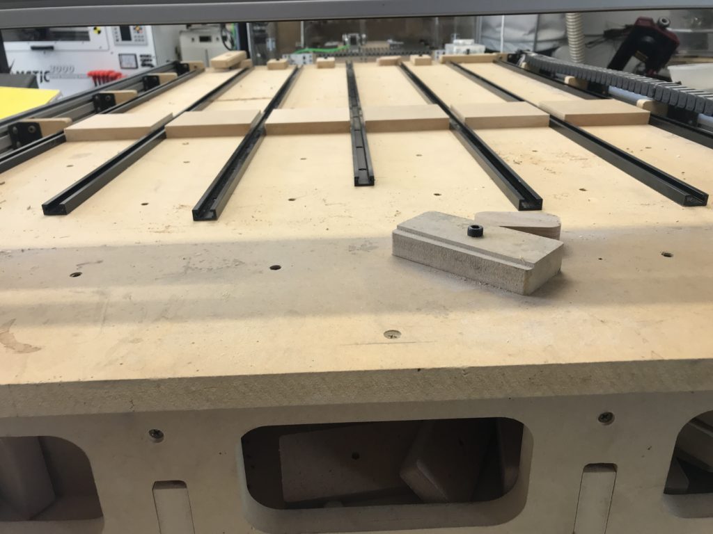
The original deck with the t-track laid out
When the original torsion box was built there were 6mm threaded inserts placed on a grid about 100mm or so. That worked fine for a few things, but I really had alot of problems trying to line things up and it was not very flexible. In the end, I ended up using a piece of 3/4 particle board as waste board and just screwing my workpieces into it. Not efficient, but effective.
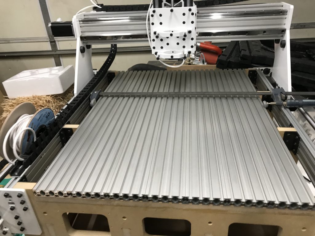
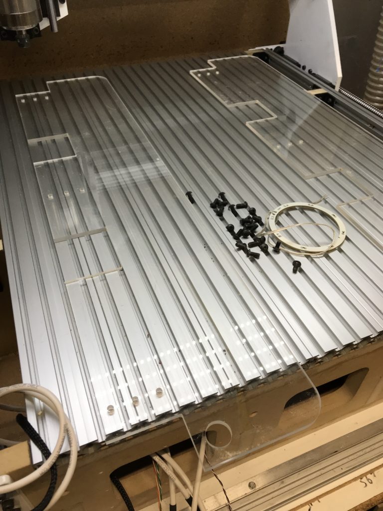
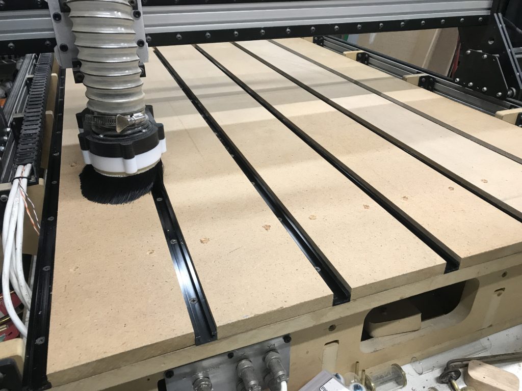
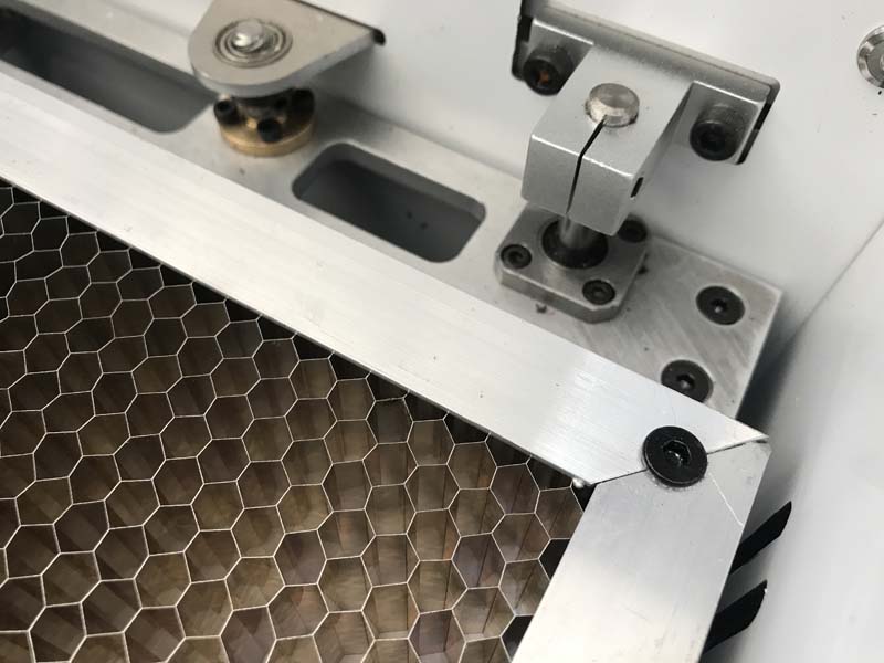
Chibi’s new deck
After I redesigned Chibi, I went with a slotted aluminum deck. This was one of those moments where you end up asking yourself why you never did it sooner. It was a total game changer. One of the main reasons that I never went with a t-track bed was that because of a design flaw with Kuro, event tho the bottom of the gantry was nearly 5″ above the deck, with a bit in it only had about 40mm of clearance. That is pitiful for trying to route anything other than plywood. But now that Kuro has a new Z axis, it has the full clearance and can make it over t-track hold downs.
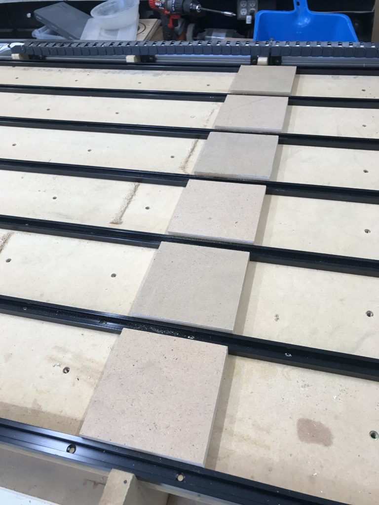
Originally I had thought of using the original inserts, but I very quickly realized that there was no way on this planet that I was ever going to get them to line up and make them and the tracks fit together tightly. So, as you can see in the picture above, i laid out the tracks where I wanted them and went to the table saw with some scrap MDF and alot of math that didn’t work so well but got me close and proceded to cut a series of blocks to test the fit. I kept shaving them down until everything sat tight. Then I went ahead and cut 6 full length slats and just like magic, they fit perfectally!
Figuring out the spacing for the layout
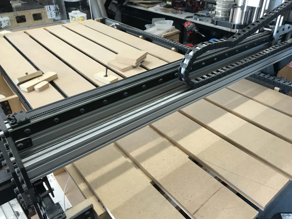
From there it was pretty easy going except for one slight hiccup, but I was saved by what turned out to be a brilliant idea (Completely unintentional of course). When I cut the slats, I cut them about a foot or so longer than I needed. The thought behind this was that I was going to use Kuro to drill all of the mounting holes. At first, I was going to do them one slat at a time, but then figured that as long as I got everything lined up, I could do it in 2 operations the first 5 sets of mounting holes, and then flip the slats around and do the last row. It sounded great in theory and in practice it worked great all except for one small thing: make sure that when creating a job, you DOUBLE CHECK to make sure that inside MOPs are actually selected to cut the inside!
With the slats overhanging
The plan was to do all of the countersinks and then do the pilot holes so I wasnt trying to plunge straight through 5/8 mdf with a 1/8 bit with a 1/2 depth of cut. Since I can’t reach the extreme ends of the deck, I lined all of the slats up to the front end of the machine. Once I cut the first 5 rows of holes, I would flip them around, mark where I needed to cut the excess, take them down on the miter saw, fasten them back down with the all of the holes I just did lined up with the back of the machine and then run one quick job to cut the first row. So the first row cut perfectally and when it got to the 2nd row all of the sudden the countersinks were huge! Well crap, it was running on the outside of sinks rather than on the inside as it was supposed to. I though for sure that I was going to have to rip another piece of MDF and what a waste. But then I realized that since I had only done the countersinks, I could just flip them over and make sure that I offset the holes to where the new ones would clear them. I took each one to the miter and cut about 100mm of each of the ends and realigned them and ran the job again this time making sure that I was actually cutting the insides of each countersink.
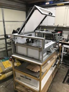
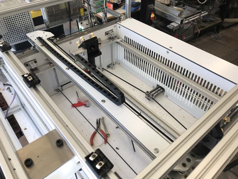
The final touches are being put on the laser. One thing that I ran across that turned out to be a huge issue is that when I build things, I tend to over engineer it and my creations end up being built like tanks. This laser is no exception. The lid ended up being pretty heavy and the first set of gas shocks I had got were rated at 10lbs each which when figuring the lifting angle was not enough. So the second set I used were rated at 20lbs apiece and that is when I ran into the problem. When I had originally designed the dibond lid piece, the intention was to just fasten the gas tube bracket straight to the dibond. That worked ok for the 10lb tubes, but when I closed the lid using the 20lb tubes, between the weight of the lid and the force of the shock, it started bowing the dibond up. Luckily the way I positioned the frame side pieces, this left me enough room to fasten a bracket mount using some left over aluminium L. I was able to use the original holes in the dibond and line them up with the new bracket which was attached to the frame rails and took the force off of the dibond. In the end, the shocks sat about 3mm lower than I had planned and slightly below horizontal, which ended up working better than expected.
before the brackets were installeduncalled for bowingmaking the new bracketsWith the new brackets installed
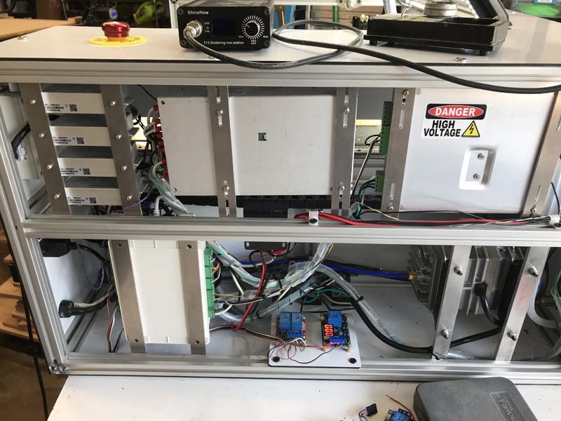
The wiring ended up being messier than I wanted, but that is the story of my life. The controller is a Cloudray Ruida RDC6432G which after a bit of some initial issues, ended up working fantastically. But more on that in the next post. The motors are Stepper Online nema 17 84oz.in 1.8º steppers. In my first version, I was using 0.9º steppers to try and increase the resolution mechanically rather than with microstepping, but somewhere along the way, they developed a very nasty whine whenever they were ran fast. I thought that it was the bearings in the wheels going out or possibly the y carriage draging somehow, but when I put the motors in this laser, they made the same noise. That was what had actually started this project in the first place. But once I switched to these motors, then all was well. The first ones I replaced them with were something like 60oz.in, but they were badly underpowered and stalled at anything over 200ipm.
The stepper drivers
The stepper drivers are StepperOnline DM420Y digital drivers. I first started using digital drivers when I did the MK3 version of my Chibi Router which uses DM542Y drivers and was blown away with how smooth and quiet they ran. Of course like every other DIY maker in the world, once you stop using arduinos to run your machines, the first stepper drivers you get are the infamous chinese TB6560 drivers which crap out if you look at them too long. Then you move to the tb6600, which if you do the power override mod on them, then they are more reliable and powerful than the 6560s, but watch out they get HOT and make sure that the resistors in them can handle the wattage, because the ones that come in them by default are woefully underrated. But when you power them on you get the awful thump of the hard power up. With digital drivers, they run MUCH cooler and have a soft power up so it does not sound like your machine is being ripped in half on startup!
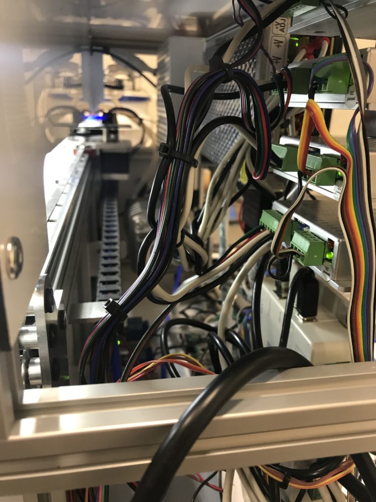
The wiring completed
To mount all of the electronics, I designed a rail system that could be used with minimal modifications for each component. When designing things, my main goals are always accessability, interoperability, reusability, and ability to transpose the part. This rail system hit all the marks. The only way it could have been better would be if i were able to only cut 10 copies of the sam part, but the screw holes were too varied to pull that off, but otherwise it works fantastically! Everything is adjustable and can slide on the inner rails so I can get my hands in there and fasten everything down.
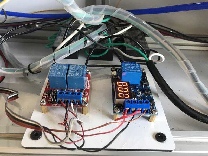
The relays
The relays ended up being the biggest facepalm part of this entire project. When I do a writeup on the software side of things, I will detail the steps I had to go throught to get my controller to work, but in the process I discovered some hidden features, one of which was a fan control timer. Of course I discovered this AFTER I had already got a time delay relay installed. What I wanted was just for the exhaust fan to run for a number of seconds after the job had completed so as to completely evacuate all of the smoke from the chamber before I opened the lid. Who would have ever thought that would be so difficult? The instructions for the relay seems to have been written in chinese and translated into half a dozen other languages before they decided to settle on english. So once you kindly signal the hiccuping giraffe until the lucky lumber is at peace (makes perfect sense right?), then and only then will the fan remain on 20 seconds past the end of the job. So after all of that, once I get it up and running, I discover that there is a hidden setting in the controller that will do exactly that. And by hidden, I am not even kidding. Burried and and completely undocumented.
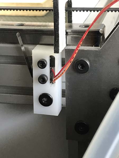
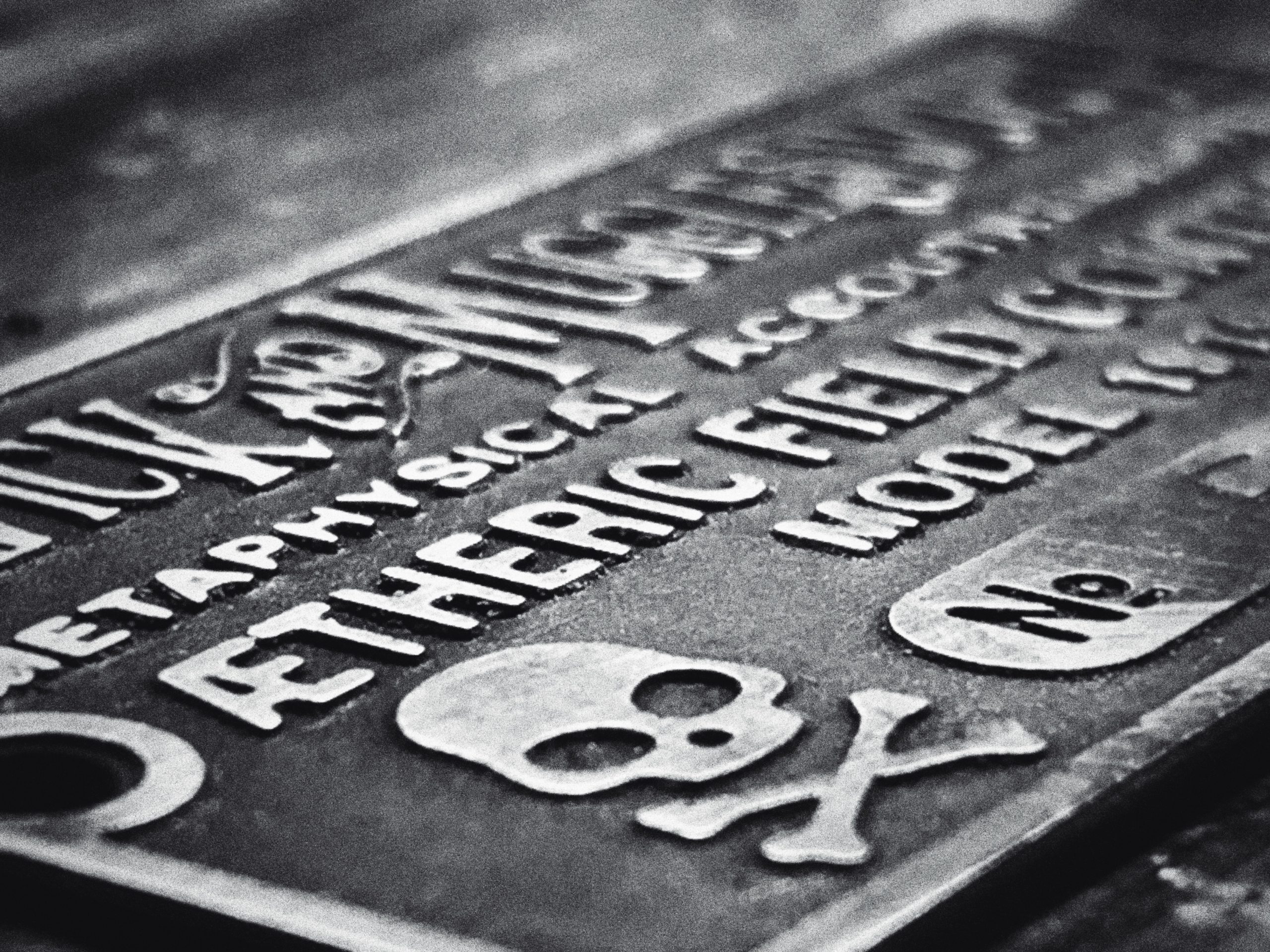
Testing the wiringHDPE limit switch holderAdding graphics to the cut plates prior to assembly
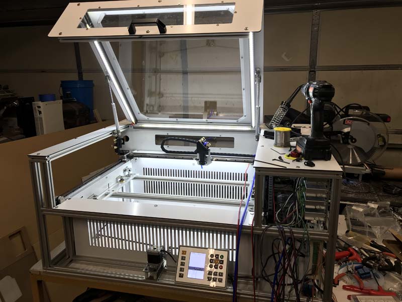
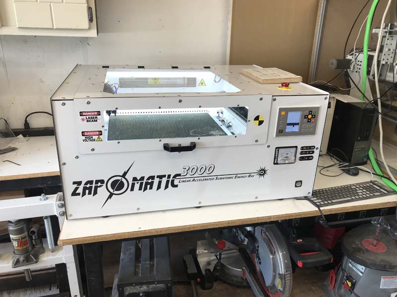
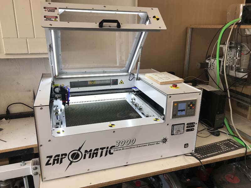
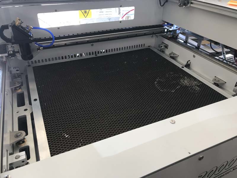
And there we have it, a finished laser engraver that works beautifully!
This is the first time that I have ever worked with aluminum dibond, so it was a bit of an adventerous learning curve. One thing that I did learn the hard way is that when using my dust collector, that it was a lifesaver for all of the small chips that came off of it, but it creates lots of long strings of plastic that got caught up in the intake of it and caused a huge rats nest. It took a couple of days to realize that I had lost alot of suction and when I was cleaning out my bag, that is when I noticed that my intake was clogged!
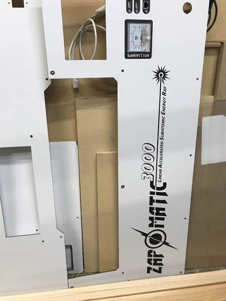
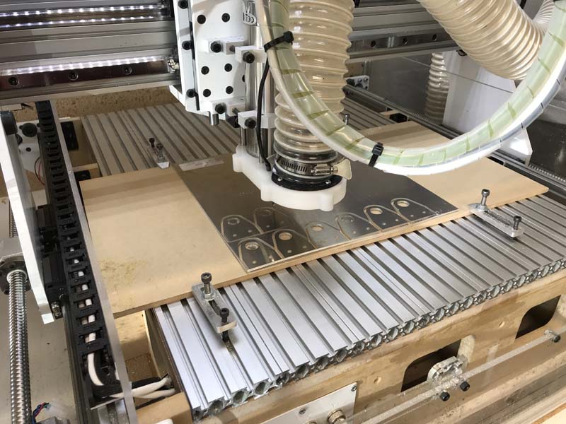
Starting to look like somethingAdding the graphics before installing was a brilliant idea!
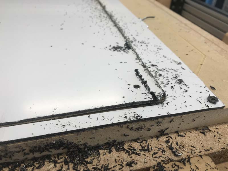
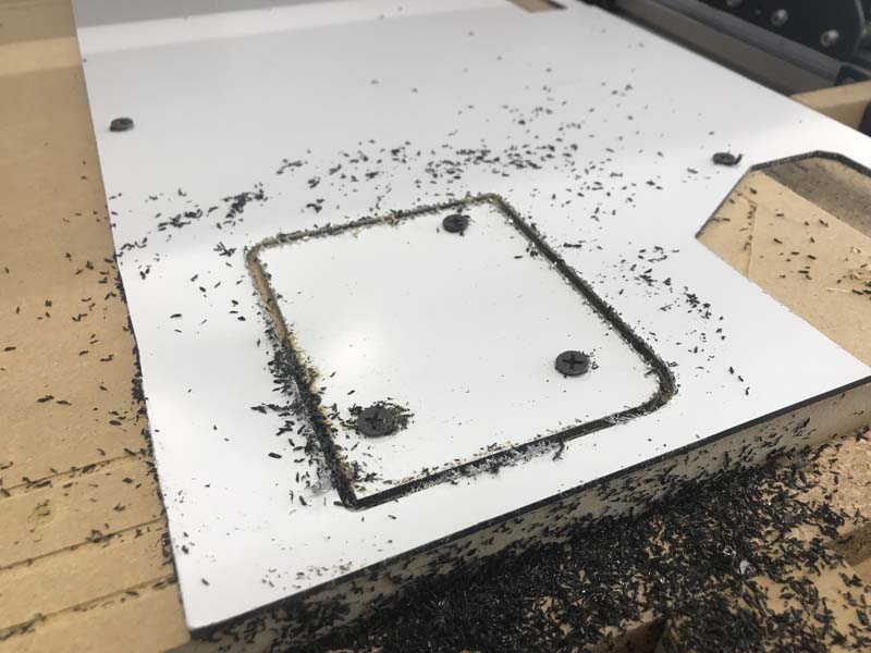
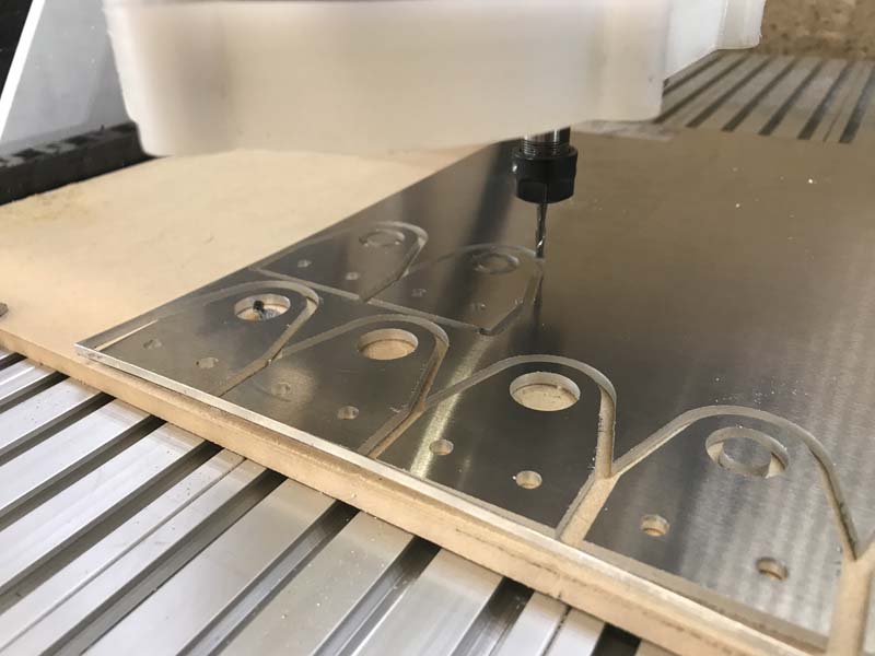
When cutting into it, overall it cuts much like hdpe maybe a little firmer. The aluminum cladding really didnt affect my cuts or speeds too much. For most things like this, I use a spiral ramp with a single cleanup pass at the bottom and I overcut the depth by about 0.25mm just to make sure that all is cut through and clean. Sometimes the aluminum will leave rougher edges because of how fast I was feeding, but that was easily cleaned up with a deburing tool. But if using one of these (which are one of the greatest tools I ever bought), just make sure that you use a light touch because once you debur the aluminum it is super easy to dig right into the composite center!
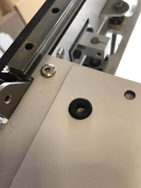
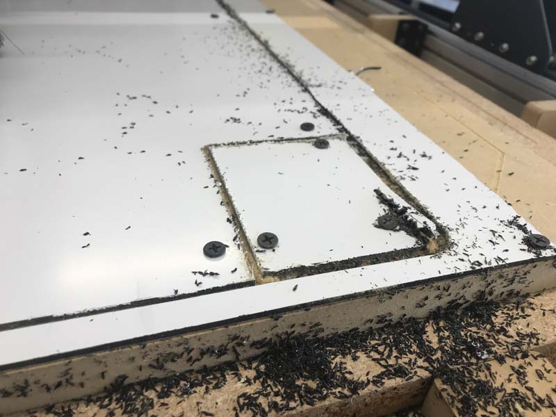
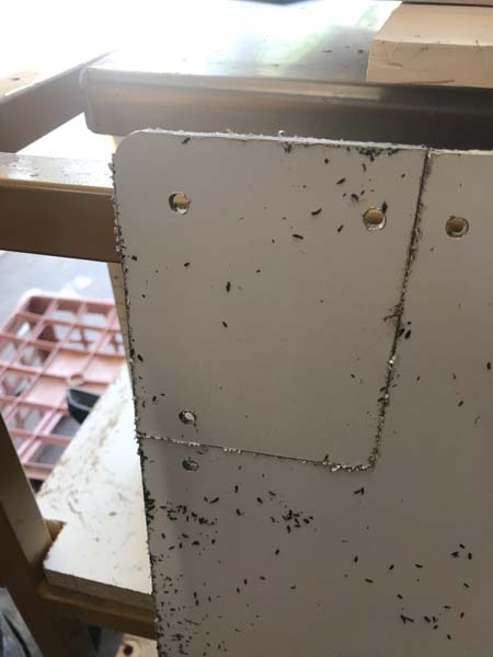
One of the other things is always make sure that your spindle is off and retracted before you make a jog! I went to jog after cutting one of the side panels and it had came up because I was just using its weight and a few screws to hold it in place and one of the corners came up and totally got ate by the bit! That was a huge let down because I had measured and only bought exactly what I needed at least for the big panels, so after much cursing and kicking things, decided that while it was still fastened down that I would cut out the corner and make an access panel right there so that I could get in and adjust the first mirror alignment without taking off the entire side panel. Not an ideal situation, but a nice recovery. Nobody saw that right?
Installing the inside panels with the z liftMore of the inside panels with the x cover installedAdding wire gromets to prevent rubbing on the through holes
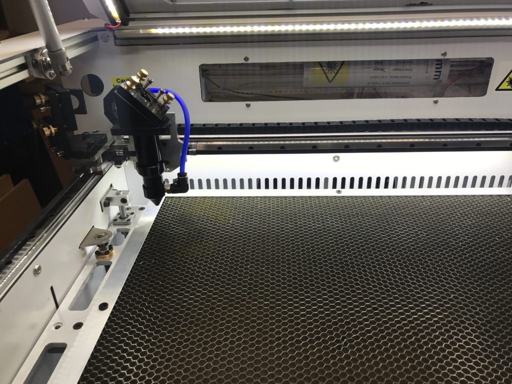
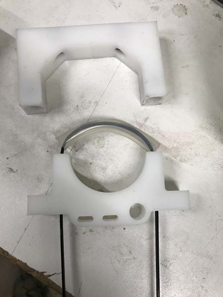
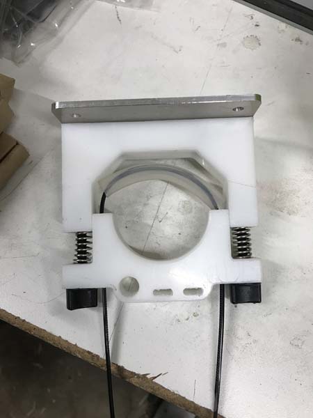
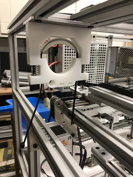
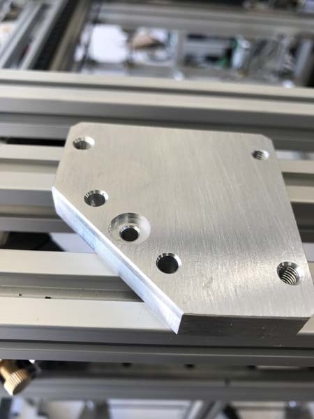
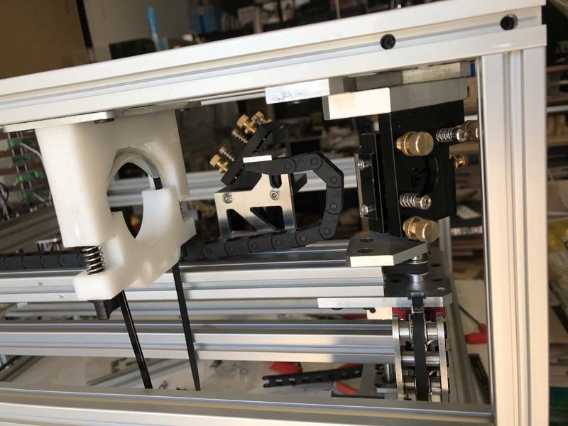
So on my original version, I really failed with this part. I wish I had pictures but the humiliation wouldn’t be worth it! Anyway, it was nothing if not a pain to keep adjusted. So my design goals with this were to make a mount that was accessable, adjustable, robust and relatively inexpensive using materials that I had lying around.
Because I wanted to keep it simple, I decided to make a two part clamp that used zip ties, 3/4 HDPE, and silicone tubing to protect the tube. When thick enough, HDPE is surprisingly stout and super easy to machine. I also desided to only make it adjustable vertically seeing as that there is only around 20mm between the laser output and the first mirror.
Centering of the beam is achieved by using the vertical adjustments on the tube mounts and the horizontal adjustment on the first mirror. This actually seemed to work out pretty well, aside from the fact that I violated the “No hidden screws” mantra that is now my life goal. But really it looked better in my mind; it always does.
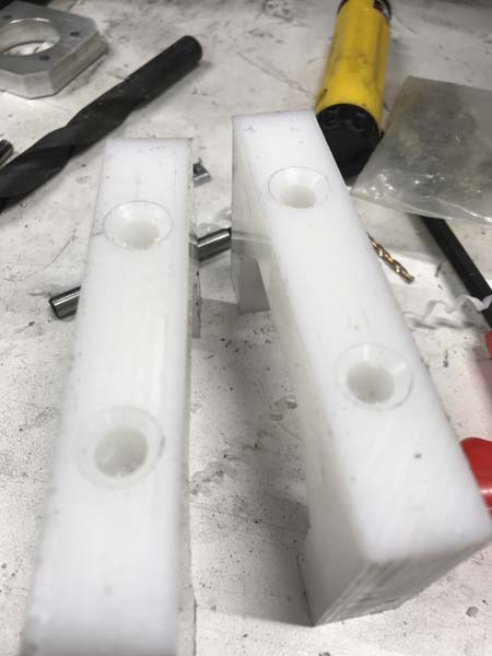
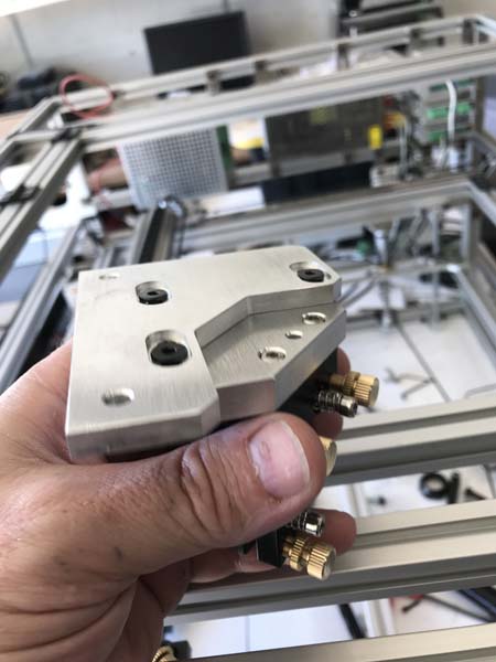
Another thing that I was focused on was cable management. The last version was a spaghetti nightmare with wires so I decided to incorporate holes in the bottom mount for keeping the cooling lines and cables organized.
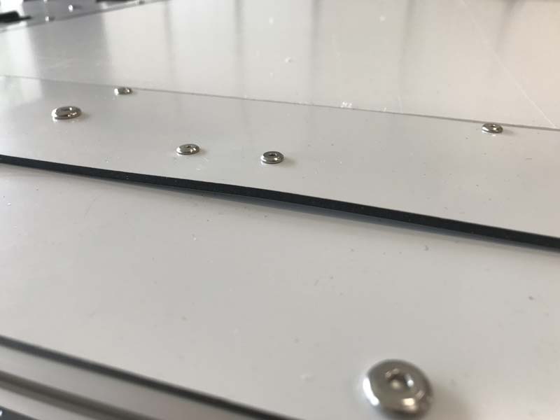
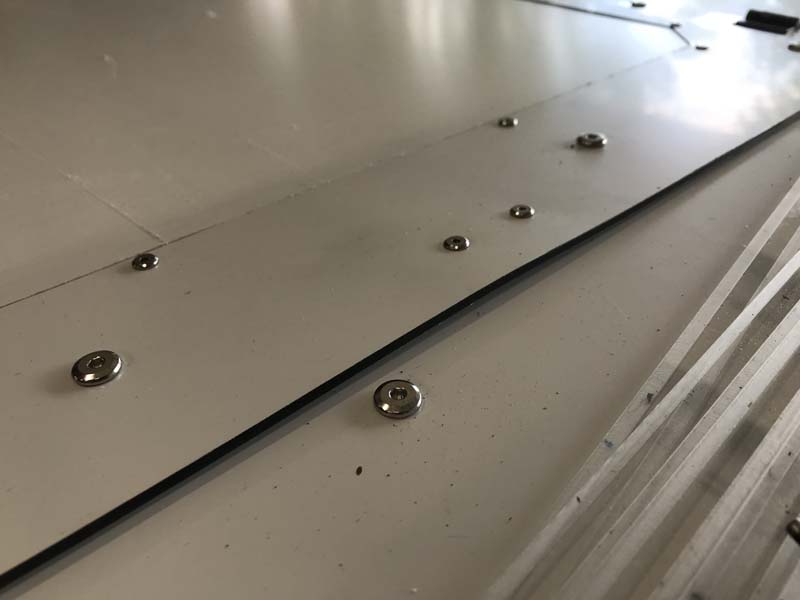
Testing the layout and fit
Closeup of the drill holes
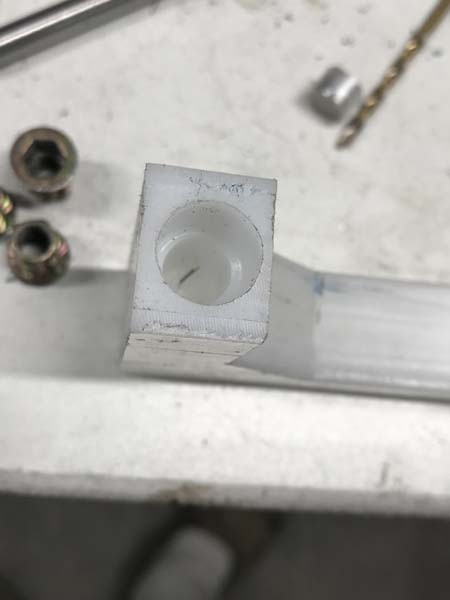
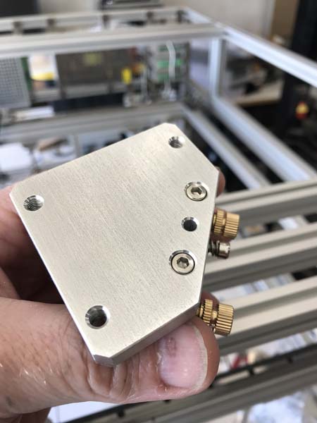
To keep the springs in place, I used a M6 threaded insert that was countersunk in a few mm to capture the ends of the springs around the screws. For the adjustment screws, I went with M6 nylon thumb screws. They work great and are non conductive, but I really did not leave much room on the inside for using them, so that would be something that I would change if I were to rebuild it in the future.
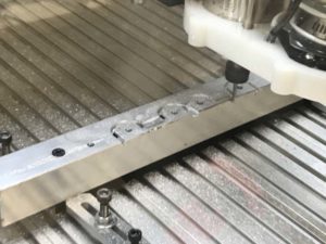
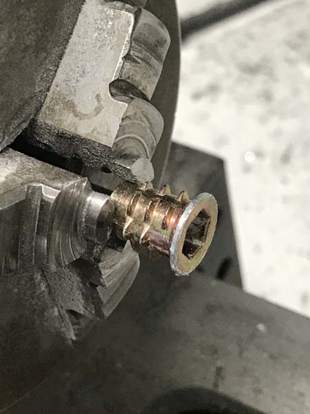
Turning down the lip around the threaded inserts
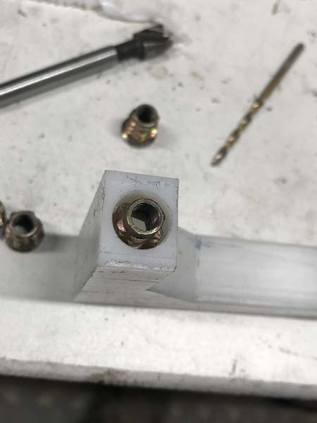
Test fitting the inserts
The inserts installed
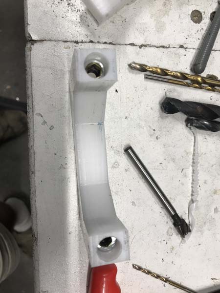
The tops countersunk for threaded inserts
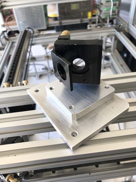
The assembled mount
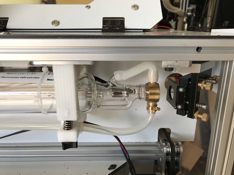
With the tube installed
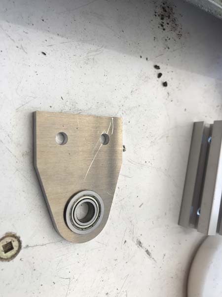
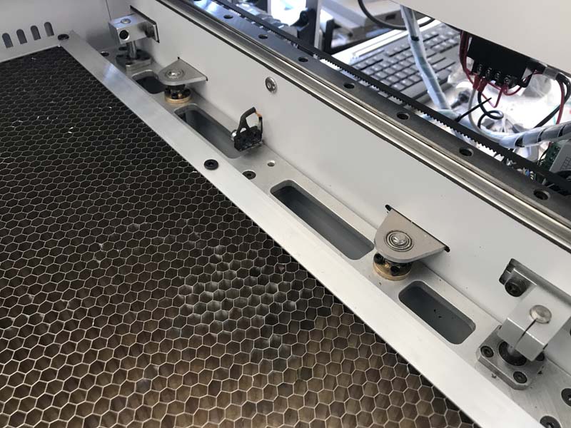
In the original engraver, the optics were from Lightobject, and worked great, but they were 23mm and I needed new mirrors and lens which is a very odd size to find. So for the price of what I was going to pay to get off sized optics, I decided to just order a complete 25mm mirror and mount set from Cloudray. The one thing that I really did not like was the way that the first mirror was mounted, which was on a long post. Although I never used it as such, it just did not seem like it was that stable and since I designed this machine to seriously haul when engraving, I thought that the vibrations would be amplified to the mirror on such a long mount. Therefore I opted to invert the first mirror so that it could be mounted from the top of the frame. This involved fabricating a new mount with adjustments and a few modifications to the actual mirror holder itself, namely drilling and tapping the other side of it for the shield. I think I should also point out that side drilling plates has always been my nemisis. So as aprehensive as I was, I went for it and surprisingly it worked!
One of the main features that I wanted to include with this laser was the ability to focus with software and/or to be able to autofocus. In the previous version, I had to use a use a distance block to focus and for different types of engraving or etching I would just sometimes have to eyeball it. That was not really great in the repeatabiliy department. Now with a z lift table I can just put a piece of material in and just press start.
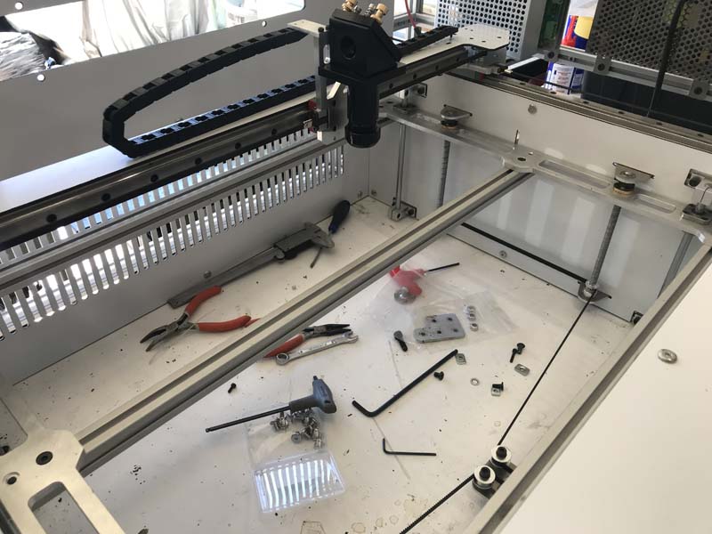
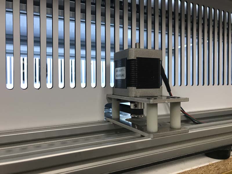
I did alot of research when it came to laser z axes, and there are a few different designs out there which had pros and cons about each one. I am not a huge fan of the scissor lift type, because I feel that the lift height to complexity ratio is not there for me. In the end I settled on just a simple screw lift with bearing rod stabilizers. Some of the factors that went into my decision was that i sometimes engrave heavy objects (granite tiles etc) so I needed a robust solution. I also wanted to be able to have a fair amount of travel so that I could etch larger objects or use things like pin stands for laser origami or whatever.
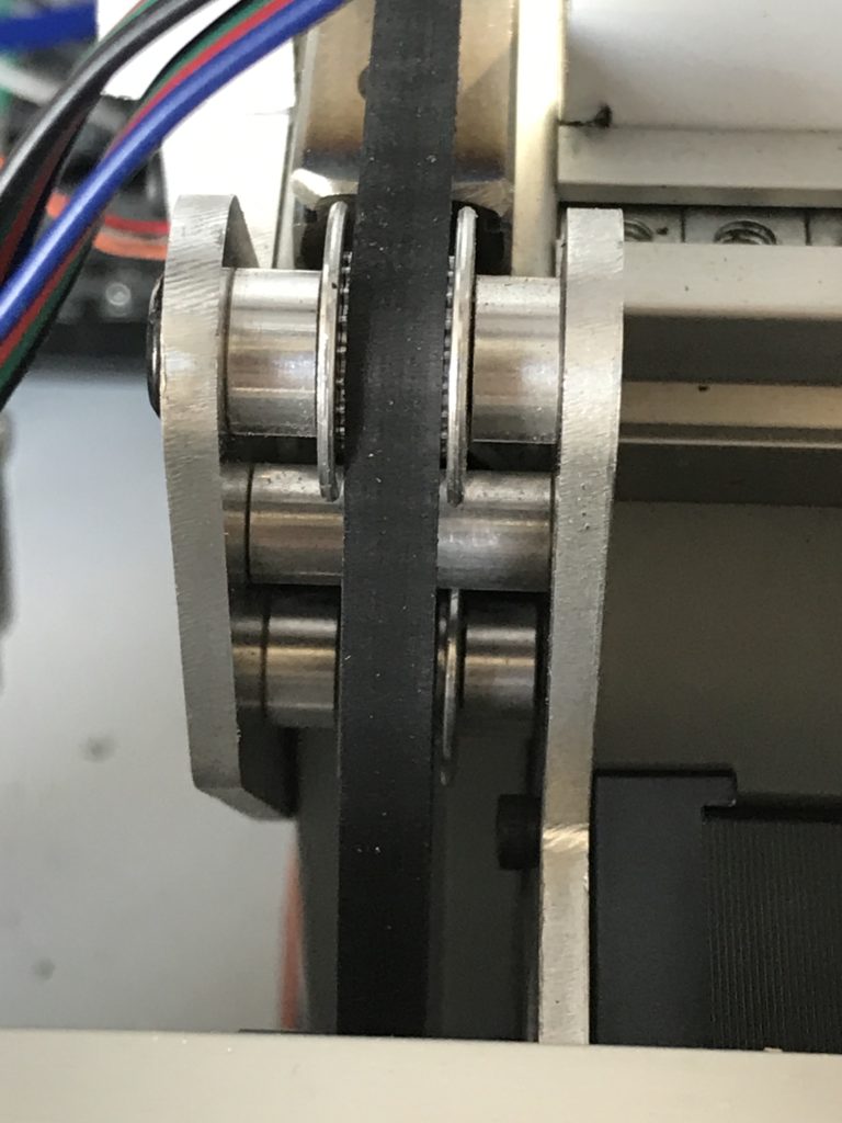
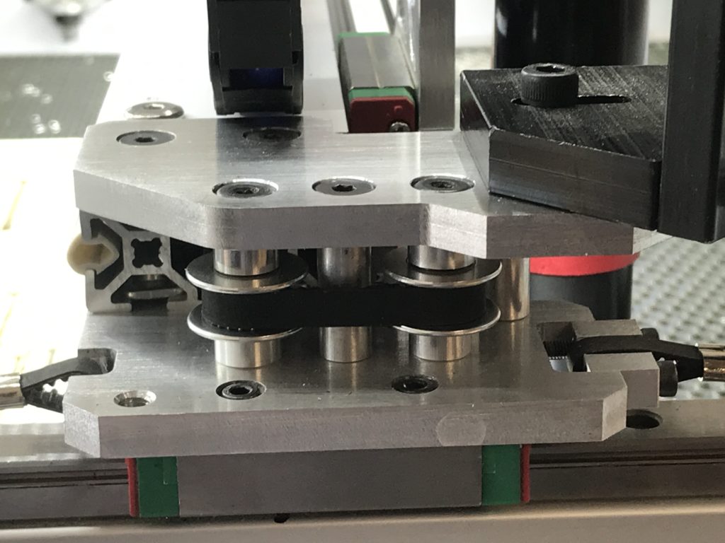
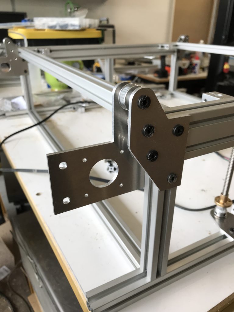
I had alot of t8 leadscrew lying around as well as some 8mm hardened rods and supports. By using four leadscrews, I was able to independently level each of the corners. Each screw it supported top and bottom with 8mm flanged bearings and kept in place with a 8mm cuff on the top and a 32t gt2 pulley on the bottom. They are all ran from a single belt through a pair of idlers to the motor with a 16t gt2 pulley. This gives me a 2:1 advantage for torque lifting heavy objects. Because the motor is in a small area in the front used for venting, I suppose that I could have gone with a nema 23, but that seemed like a bit of overkill and besides I had a pile of 17s lying around, so that seemed like the obvious choice. Waste not, want not, make cheap laser or something like that…
Cutting out the leadscrew bracketsOne of the brackets with the bearing installedTest fitting the leadscrewsThe motor mountedAnd then the finished z table
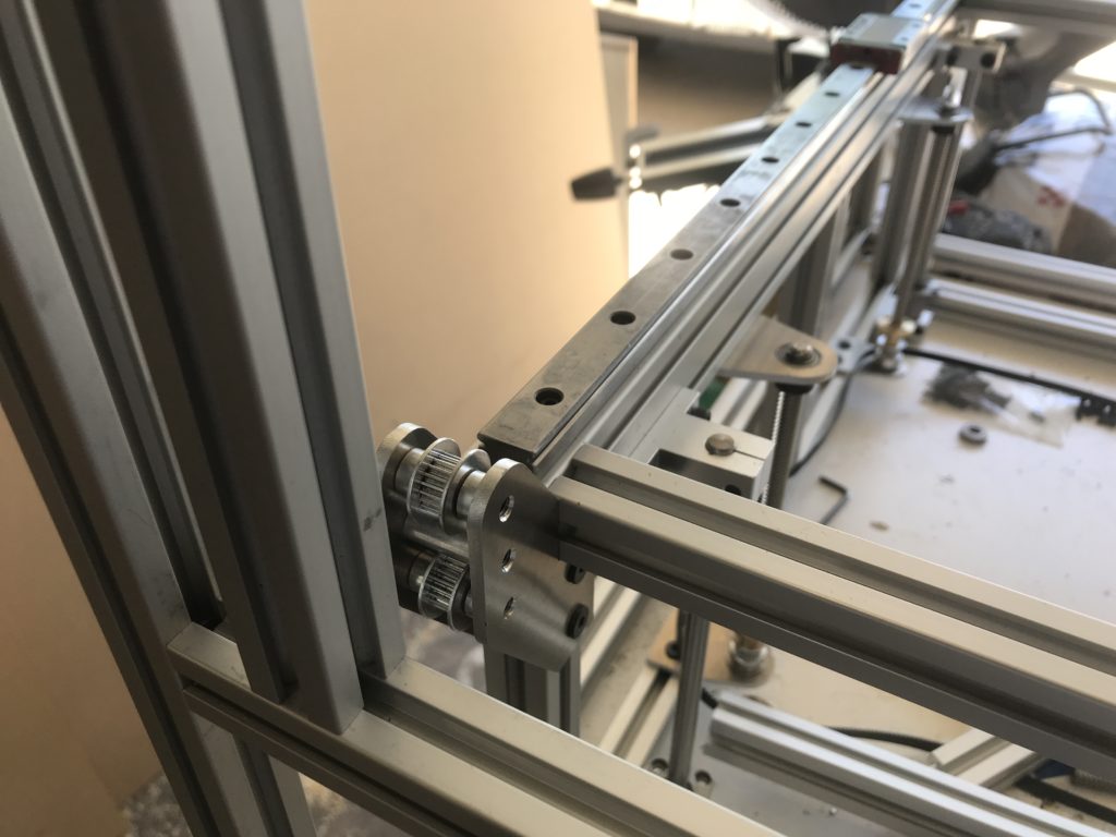
So now the laser is continuing on nicely. There are some things that I really would have liked to change, but at the same time I am working on a budget, so I tried to repurpose as many parts that I had lying around as possible. Some of the things i would have changed is for the linear rail, I would have went with something a bit lighter such as MGN9 vs the MGN15 that I used. But, I had them on hand and didnt want to shell out for new rail. I was already in it for a bit with the aluminum dibond.
MGN15 rail fits nicely but is a bit heavier than i would like
Also I would have really liked to have gone with 10mm gt2 belts as opposed to the 6mm ones that I used. But I can change that at a later date just by switching out the pulleys, idlers, and spacers. It will require an almost complete teardown and rebuild, but in the mean time I will see how these 6mm belts hold. It has been my experience that they wear and stretch much faster than their 10mm counterparts.
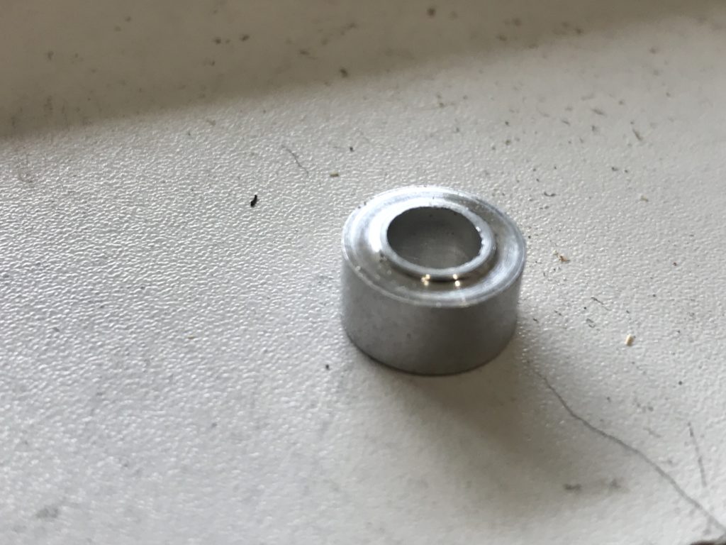
One thing tho, making the spacers was a bit of a pain. In the early days, Openbuilds tended to be very inconsistant with their offerings. It would seem that everytime that I would order, I never got the same thing twice. For a while, their spacers would either be excessively thick or super thin walled. The problem witht the thin wall ones is that they would wander and not sit directly on the hub of the bearings and drag on the bearing cover. Also, if they were meant to take stress, they would tend to crumple at the ends. The super thick ones on the other hand, fit nicely on the bolt, but sometimes would get in the way. So my solution was to take a few of the 6.35mm spacers and turn them down to 5mm with a small lip on the contact side of the idler which acted like a built in washer to keep it from rubbing on the outer race of the idler.
One of the spacers after they got turned downclose up of the spacers and idlers assembled
For the actual spacers, I just used stock 20mm aluminum spacers to take the structural load and act as crush washers so that there was about 0.25mm of play between the idlers and the top and bottom spacers which allows the belt to find its own alignment.
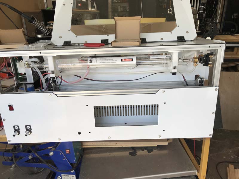
So this will begin to detail the process of rebuilding my laser engraver. The original incantation started off being more of a proof of concept and was only the second machine that i ever designed, so it was at best both unfinished and flawed. It was 40w and based heavily on the 2.x Laser from Bart Dring at buildlog.net. It worked well and introduced me into the world of laser engraving and cutting.
But, some of the obvious flaws were that it was controlled by LinuxCNC, which while amazing for cnc machines, it lacks in the laser department. Vector engraving was easy enough, but raster engraving was next to impossible with any degree of accuracy. I was using an extension from Ben Jackson and Jeremy Van Grinsven that allowed laser rastering using a “magic z” approach. Late last year i started upgrading all of my machines to Mesa control cards, specifically a 7i96, and because of the speed reqiured to fire the laser vs the transfer rate over ethernet, it ended up breaking the whole system. Then end the middle of reworking the laser, it ended up getting -15º and for the first time it froze inside of my garage and cracked the water jacket on the laser tube.
So that cemented my decision to go with an DSP controller and at the same time, do away with makerslide/openV configuration. While OpenV is pretty awesome for quickly cobbling together machines, I have found that there are some pretty glaring flaws with it, namely its weakness when dealing with lateral forces. Also it is super easy to deform the rails when tightening insertion nuts. This has caused many a bumpy road when trying to adjust an endstop!
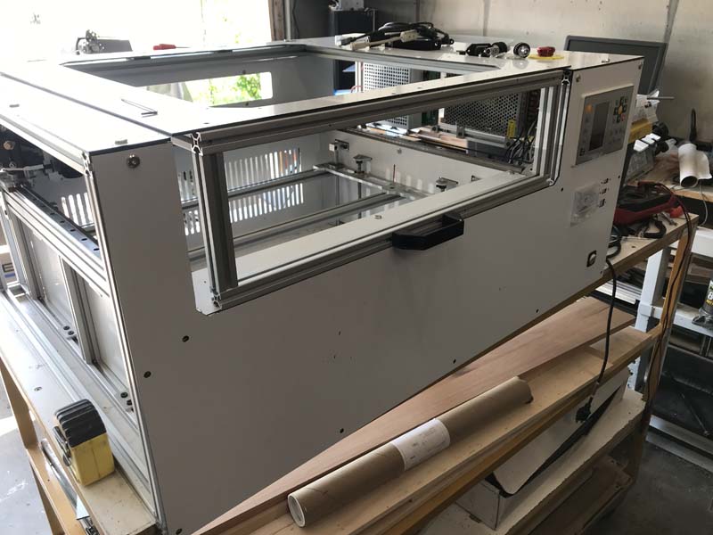
While surfing around looking for design inspirations, i stumbled across this one on instructables called the R-Laser 6020 and i was amazed at the attention to detail and clean engineering that went into it. I also learned what aluminum dibond was and there is a plastics supplier in Denver that sells sheets of it pretty reasonably. But there were also a few things about it that i thought that i could improve upon. I wanted to design something that was entirely self contained because i was not a huge fan of the 2 part machine / electronics cabinet. My space is limited and i could build one that would fit entirely on a workbench, albiet a wide one. The other thing i wanted to change was the lid. Something that opens both top and front would be easier to place objects inside of it and get them situated. And of course the z table would have to me much more stout because i do engrave on granite tiles which can be quite heavy.
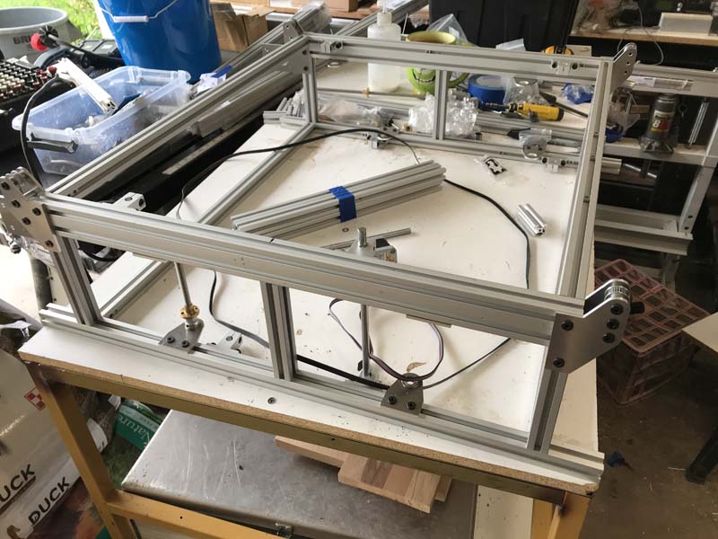
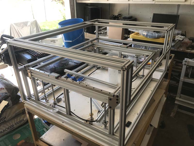
so after a waiting for my Misumi order, here is the frame. The rails are MGN15 rails which are bigger than i wanted to go, but they were what i had and i really did not feel like waiting weeks for to order them from RobotDigg and i was trying to stay within a budget as well.
The Y motor mountsThe Internal frame
The overall design is an internal frame with a external cage to give it stability. The z axis was really designed around a handful of parts i had lying around, and mostly a long belt that would be able to turn 4 T8 threaded rods at the same time and used 8mm smooth rods for the guides.