So after getting tired of trying to fasten parts down to the wasteboard and my wasteboard bowing, I finally decided to actually create a rail system for my bigger router. I had toyed with the idea for a while, but truthfully I have been lazy and not very motivated. Winter is a bad time of year for me and in the fall I begin to start feeling down and this year has been a rough one with the city waging war against me, having to move next year, and of course losing my best buddy Damage…

So in order to get me up and moving, I have been giving myself projects that are not too difficult that I can complete with few if any problems to keep my frustration quotient low and keep me moving otherwise I might end up melting into whatever I am sitting on. As part of my continuing upgrade of my larger router, I decided to redo the deck and fastening system.
Now keep in mind that this is just a temporary upgrade because I have never been satisfied with this design and on the next iteration, not only will it be larger, I will be doing away with the v-wheels and the belt drive. Those are both good for low cost and simple machines, but some of the things that I have been doing are beginning to test the limits of both systems. I am not sure if I will be going to fully suported bearings or linear rail, but right now both are being considered. As for the belt drive, I am just beating a dead horse with that one. On the one hand, it is fast, but it is anything but accurate. I have to recalibrate it at least once a month.
So in the future, I am pretty decided that I will be going with a rack and pinion. For my purposes, it should run just as fast which considering that I am wanting to go at least 4×8 and will only be using it for wood or acrylic, speed is definitely huge factor. At that size I am fine with a small loss of accuracy for a huge gain in speed. The other big change will be going from steppers to servos. I think I have gone as far as steppers can take me both in terms of speed, accuracy, and torque and now it is time to go to the next level.
When the original torsion box was built there were 6mm threaded inserts placed on a grid about 100mm or so. That worked fine for a few things, but I really had alot of problems trying to line things up and it was not very flexible. In the end, I ended up using a piece of 3/4 particle board as waste board and just screwing my workpieces into it. Not efficient, but effective.
After I redesigned Chibi, I went with a slotted aluminum deck. This was one of those moments where you end up asking yourself why you never did it sooner. It was a total game changer. One of the main reasons that I never went with a t-track bed was that because of a design flaw with Kuro, event tho the bottom of the gantry was nearly 5″ above the deck, with a bit in it only had about 40mm of clearance. That is pitiful for trying to route anything other than plywood. But now that Kuro has a new Z axis, it has the full clearance and can make it over t-track hold downs.
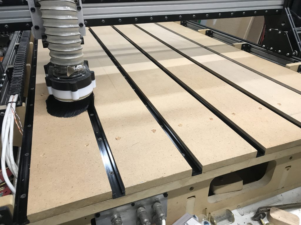
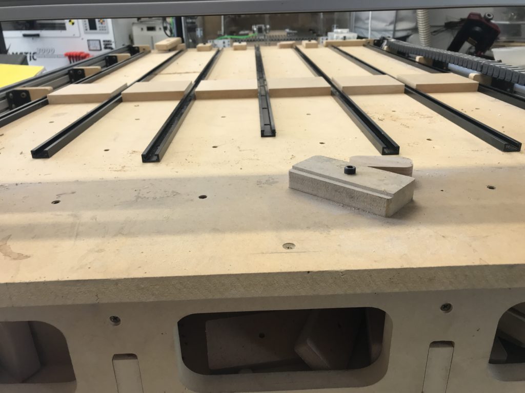
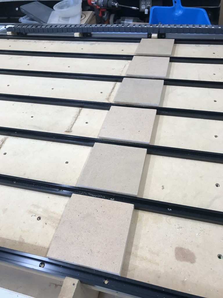
Originally I had thought of using the original inserts, but I very quickly realized that there was no way on this planet that I was ever going to get them to line up and make them and the tracks fit together tightly. So, as you can see in the picture above, i laid out the tracks where I wanted them and went to the table saw with some scrap MDF and alot of math that didn’t work so well but got me close and proceded to cut a series of blocks to test the fit. I kept shaving them down until everything sat tight. Then I went ahead and cut 6 full length slats and just like magic, they fit perfectally!
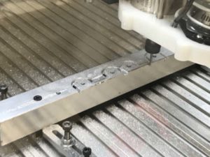
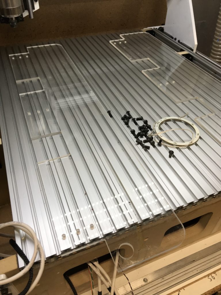
From there it was pretty easy going except for one slight hiccup, but I was saved by what turned out to be a brilliant idea (Completely unintentional of course). When I cut the slats, I cut them about a foot or so longer than I needed. The thought behind this was that I was going to use Kuro to drill all of the mounting holes. At first, I was going to do them one slat at a time, but then figured that as long as I got everything lined up, I could do it in 2 operations the first 5 sets of mounting holes, and then flip the slats around and do the last row. It sounded great in theory and in practice it worked great all except for one small thing: make sure that when creating a job, you DOUBLE CHECK to make sure that inside MOPs are actually selected to cut the inside!
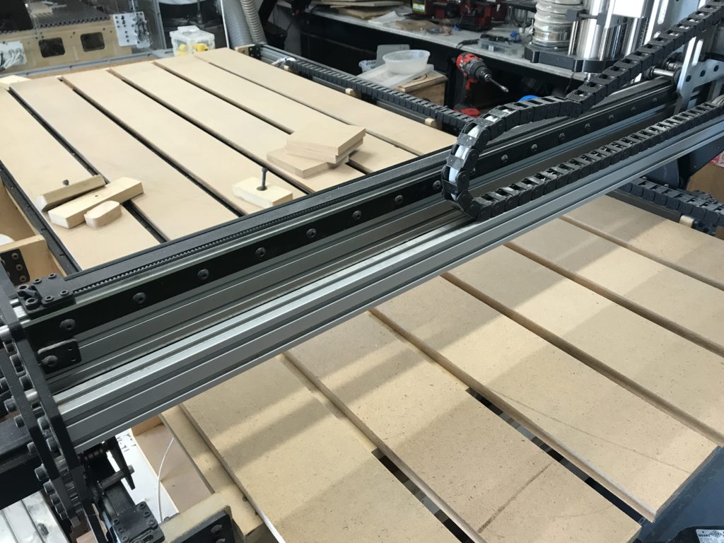
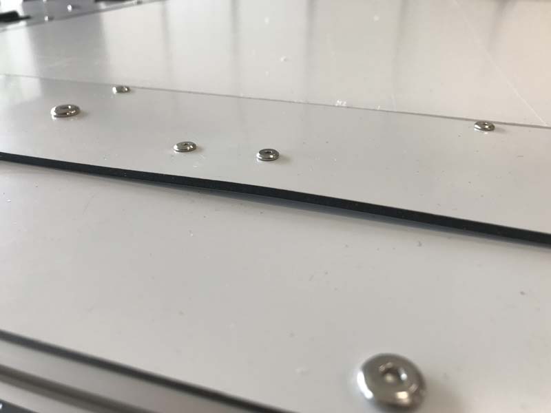
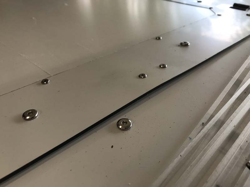
The plan was to do all of the countersinks and then do the pilot holes so I wasnt trying to plunge straight through 5/8 mdf with a 1/8 bit with a 1/2 depth of cut. Since I can’t reach the extreme ends of the deck, I lined all of the slats up to the front end of the machine. Once I cut the first 5 rows of holes, I would flip them around, mark where I needed to cut the excess, take them down on the miter saw, fasten them back down with the all of the holes I just did lined up with the back of the machine and then run one quick job to cut the first row. So the first row cut perfectally and when it got to the 2nd row all of the sudden the countersinks were huge! Well crap, it was running on the outside of sinks rather than on the inside as it was supposed to. I though for sure that I was going to have to rip another piece of MDF and what a waste. But then I realized that since I had only done the countersinks, I could just flip them over and make sure that I offset the holes to where the new ones would clear them. I took each one to the miter and cut about 100mm of each of the ends and realigned them and ran the job again this time making sure that I was actually cutting the insides of each countersink.