So on my original version, I really failed with this part. I wish I had pictures but the humiliation wouldn’t be worth it! Anyway, it was nothing if not a pain to keep adjusted. So my design goals with this were to make a mount that was accessable, adjustable, robust and relatively inexpensive using materials that I had lying around.
Because I wanted to keep it simple, I decided to make a two part clamp that used zip ties, 3/4 HDPE, and silicone tubing to protect the tube. When thick enough, HDPE is surprisingly stout and super easy to machine. I also desided to only make it adjustable vertically seeing as that there is only around 20mm between the laser output and the first mirror.
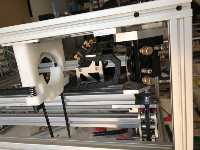
Centering of the beam is achieved by using the vertical adjustments on the tube mounts and the horizontal adjustment on the first mirror. This actually seemed to work out pretty well, aside from the fact that I violated the “No hidden screws” mantra that is now my life goal. But really it looked better in my mind; it always does.
Another thing that I was focused on was cable management. The last version was a spaghetti nightmare with wires so I decided to incorporate holes in the bottom mount for keeping the cooling lines and cables organized.
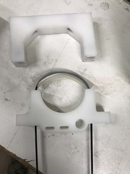
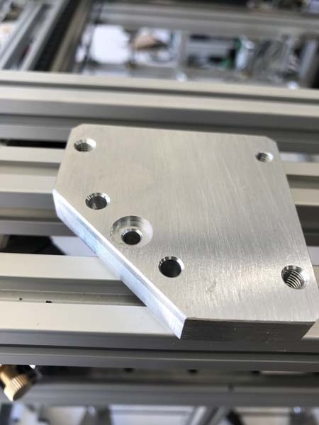
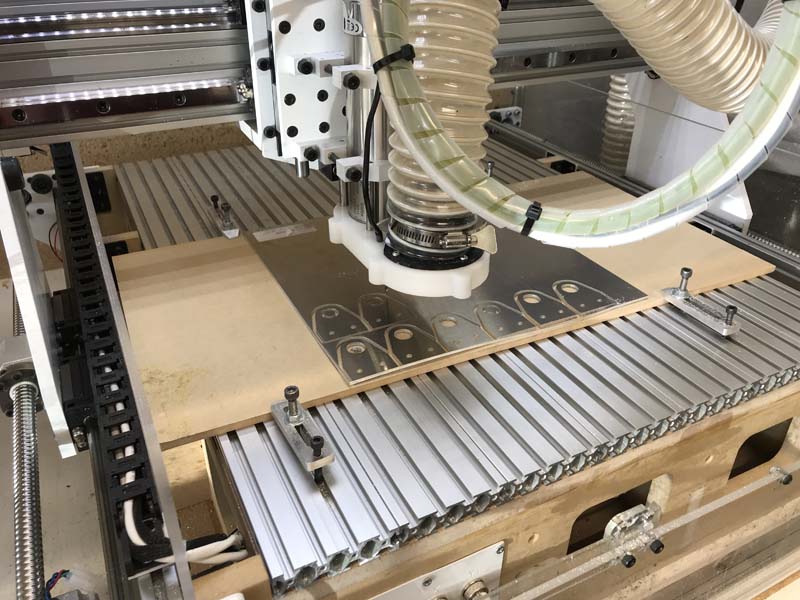
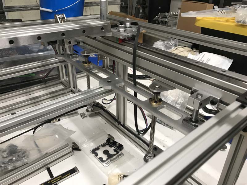
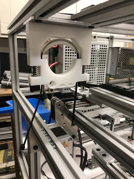
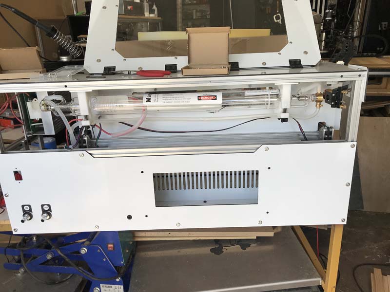
Testing the layout and fit
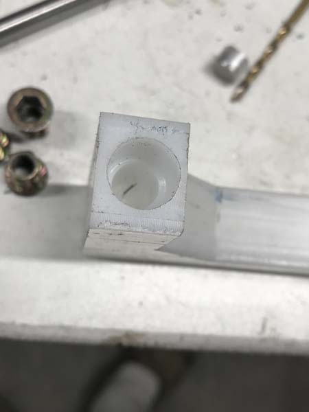
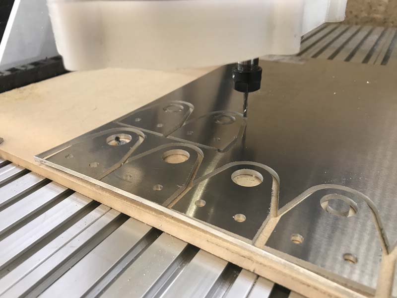
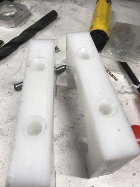
Closeup of the drill holes
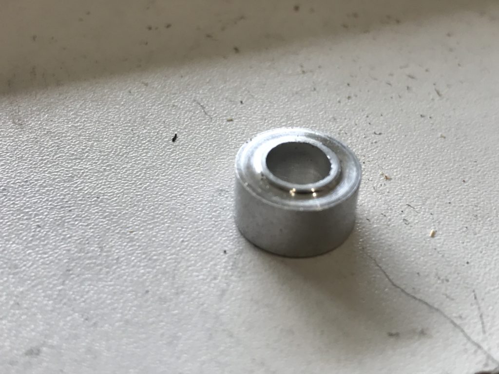
To keep the springs in place, I used a M6 threaded insert that was countersunk in a few mm to capture the ends of the springs around the screws. For the adjustment screws, I went with M6 nylon thumb screws. They work great and are non conductive, but I really did not leave much room on the inside for using them, so that would be something that I would change if I were to rebuild it in the future.
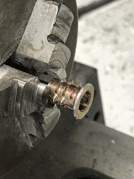
Turning down the lip around the threaded inserts
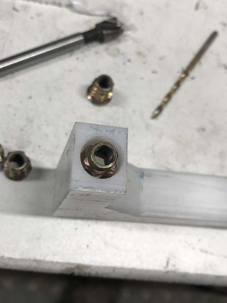
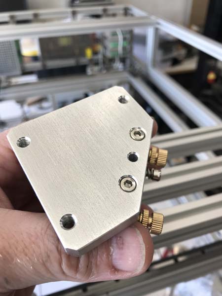
Test fitting the inserts
The inserts installed
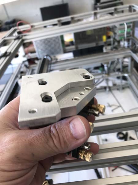
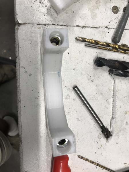
The tops countersunk for threaded inserts
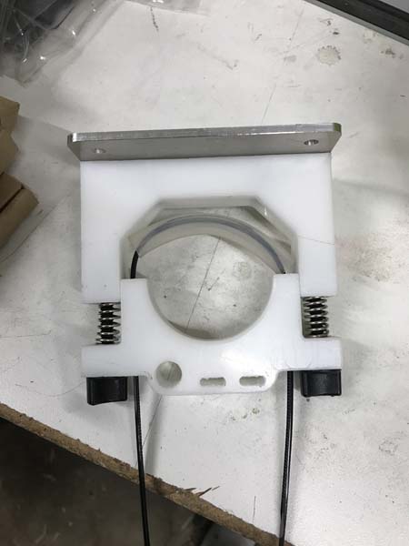
The assembled mount
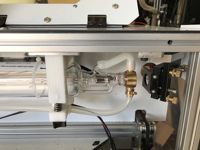
With the tube installed
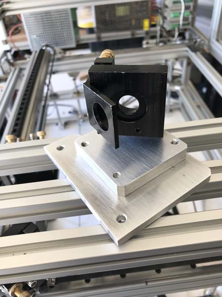
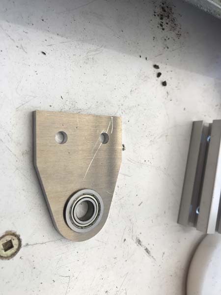
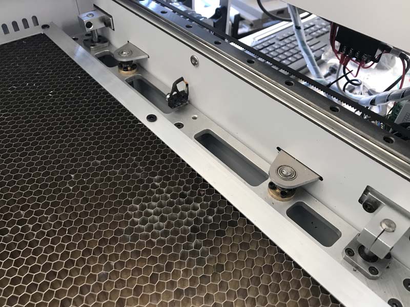
In the original engraver, the optics were from Lightobject, and worked great, but they were 23mm and I needed new mirrors and lens which is a very odd size to find. So for the price of what I was going to pay to get off sized optics, I decided to just order a complete 25mm mirror and mount set from Cloudray. The one thing that I really did not like was the way that the first mirror was mounted, which was on a long post. Although I never used it as such, it just did not seem like it was that stable and since I designed this machine to seriously haul when engraving, I thought that the vibrations would be amplified to the mirror on such a long mount. Therefore I opted to invert the first mirror so that it could be mounted from the top of the frame. This involved fabricating a new mount with adjustments and a few modifications to the actual mirror holder itself, namely drilling and tapping the other side of it for the shield. I think I should also point out that side drilling plates has always been my nemisis. So as aprehensive as I was, I went for it and surprisingly it worked!