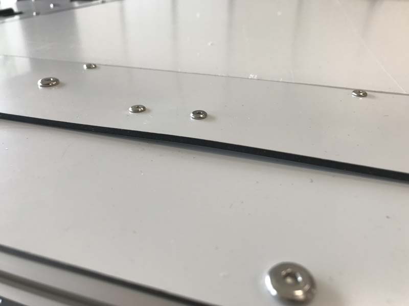
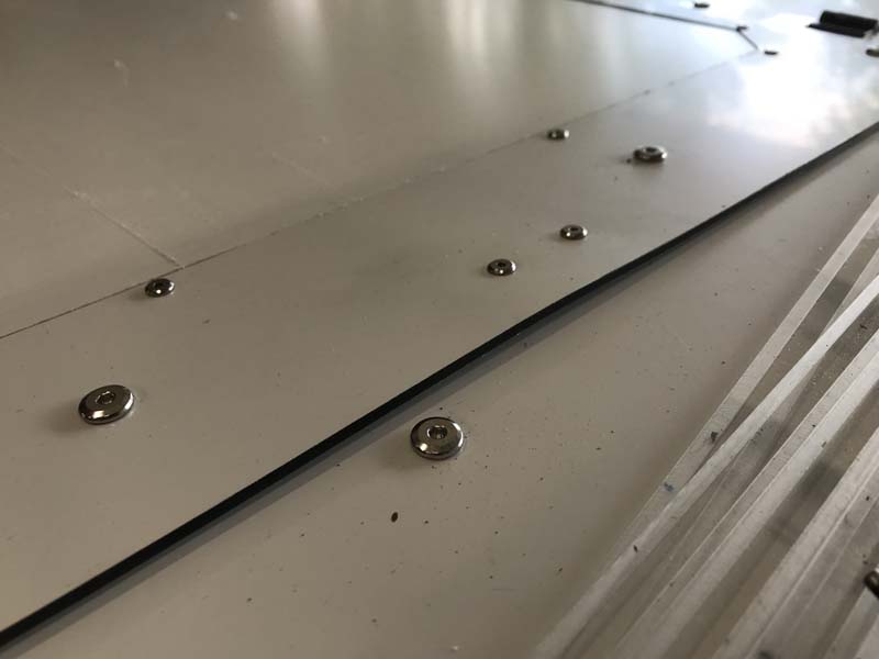
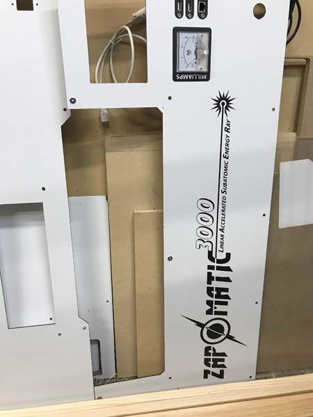
The final touches are being put on the laser. One thing that I ran across that turned out to be a huge issue is that when I build things, I tend to over engineer it and my creations end up being built like tanks. This laser is no exception. The lid ended up being pretty heavy and the first set of gas shocks I had got were rated at 10lbs each which when figuring the lifting angle was not enough. So the second set I used were rated at 20lbs apiece and that is when I ran into the problem. When I had originally designed the dibond lid piece, the intention was to just fasten the gas tube bracket straight to the dibond. That worked ok for the 10lb tubes, but when I closed the lid using the 20lb tubes, between the weight of the lid and the force of the shock, it started bowing the dibond up. Luckily the way I positioned the frame side pieces, this left me enough room to fasten a bracket mount using some left over aluminium L. I was able to use the original holes in the dibond and line them up with the new bracket which was attached to the frame rails and took the force off of the dibond. In the end, the shocks sat about 3mm lower than I had planned and slightly below horizontal, which ended up working better than expected.
The wiring ended up being messier than I wanted, but that is the story of my life. The controller is a Cloudray Ruida RDC6432G which after a bit of some initial issues, ended up working fantastically. But more on that in the next post. The motors are Stepper Online nema 17 84oz.in 1.8º steppers. In my first version, I was using 0.9º steppers to try and increase the resolution mechanically rather than with microstepping, but somewhere along the way, they developed a very nasty whine whenever they were ran fast. I thought that it was the bearings in the wheels going out or possibly the y carriage draging somehow, but when I put the motors in this laser, they made the same noise. That was what had actually started this project in the first place. But once I switched to these motors, then all was well. The first ones I replaced them with were something like 60oz.in, but they were badly underpowered and stalled at anything over 200ipm.
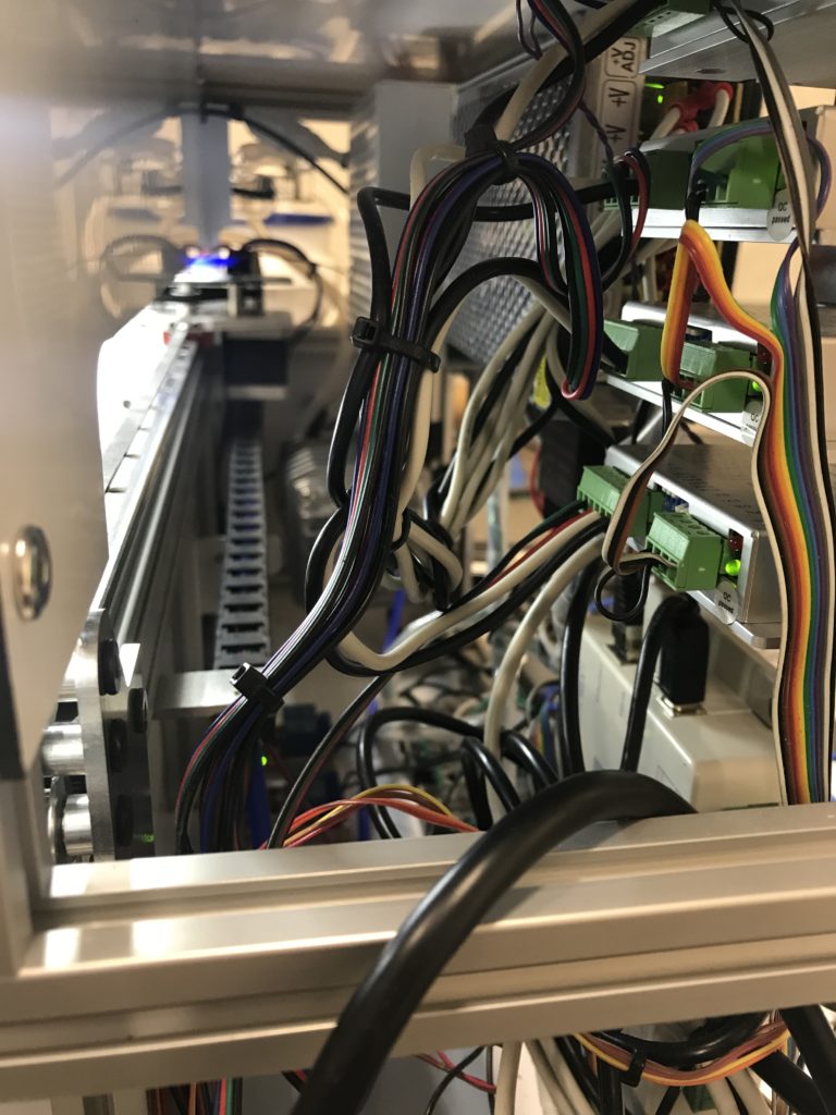
The stepper drivers are StepperOnline DM420Y digital drivers. I first started using digital drivers when I did the MK3 version of my Chibi Router which uses DM542Y drivers and was blown away with how smooth and quiet they ran. Of course like every other DIY maker in the world, once you stop using arduinos to run your machines, the first stepper drivers you get are the infamous chinese TB6560 drivers which crap out if you look at them too long. Then you move to the tb6600, which if you do the power override mod on them, then they are more reliable and powerful than the 6560s, but watch out they get HOT and make sure that the resistors in them can handle the wattage, because the ones that come in them by default are woefully underrated. But when you power them on you get the awful thump of the hard power up. With digital drivers, they run MUCH cooler and have a soft power up so it does not sound like your machine is being ripped in half on startup!
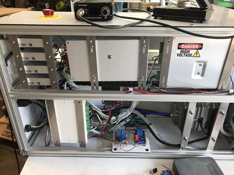
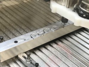
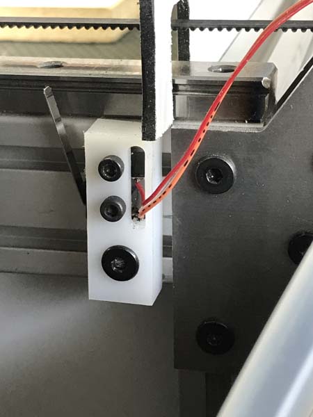
To mount all of the electronics, I designed a rail system that could be used with minimal modifications for each component. When designing things, my main goals are always accessability, interoperability, reusability, and ability to transpose the part. This rail system hit all the marks. The only way it could have been better would be if i were able to only cut 10 copies of the sam part, but the screw holes were too varied to pull that off, but otherwise it works fantastically! Everything is adjustable and can slide on the inner rails so I can get my hands in there and fasten everything down.
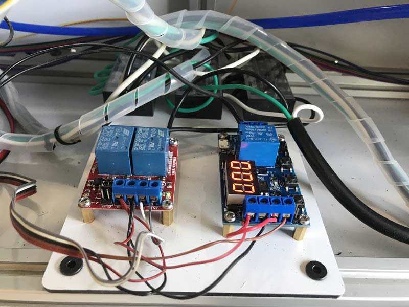
The relays ended up being the biggest facepalm part of this entire project. When I do a writeup on the software side of things, I will detail the steps I had to go throught to get my controller to work, but in the process I discovered some hidden features, one of which was a fan control timer. Of course I discovered this AFTER I had already got a time delay relay installed. What I wanted was just for the exhaust fan to run for a number of seconds after the job had completed so as to completely evacuate all of the smoke from the chamber before I opened the lid. Who would have ever thought that would be so difficult? The instructions for the relay seems to have been written in chinese and translated into half a dozen other languages before they decided to settle on english. So once you kindly signal the hiccuping giraffe until the lucky lumber is at peace (makes perfect sense right?), then and only then will the fan remain on 20 seconds past the end of the job. So after all of that, once I get it up and running, I discover that there is a hidden setting in the controller that will do exactly that. And by hidden, I am not even kidding. Burried and and completely undocumented.
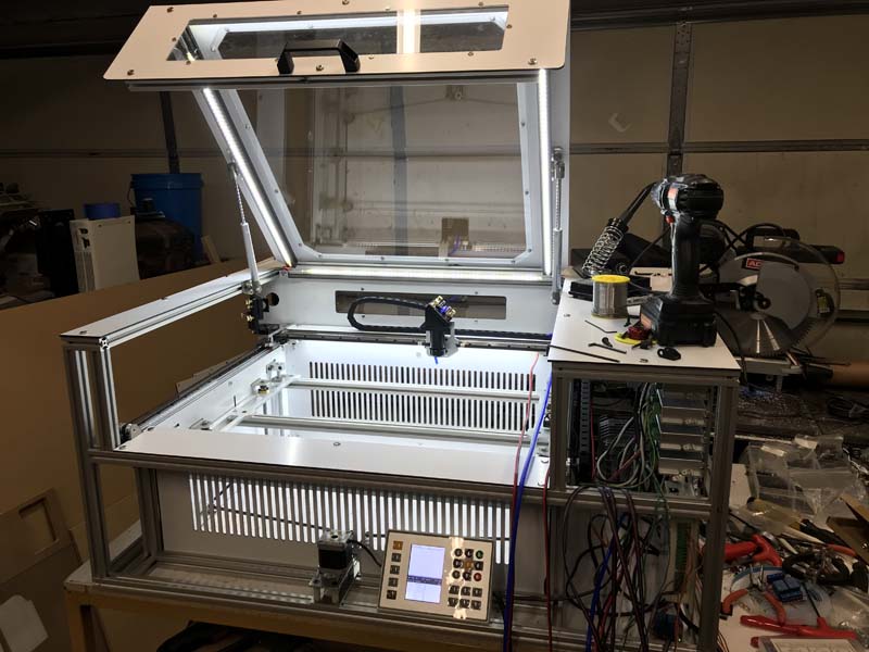
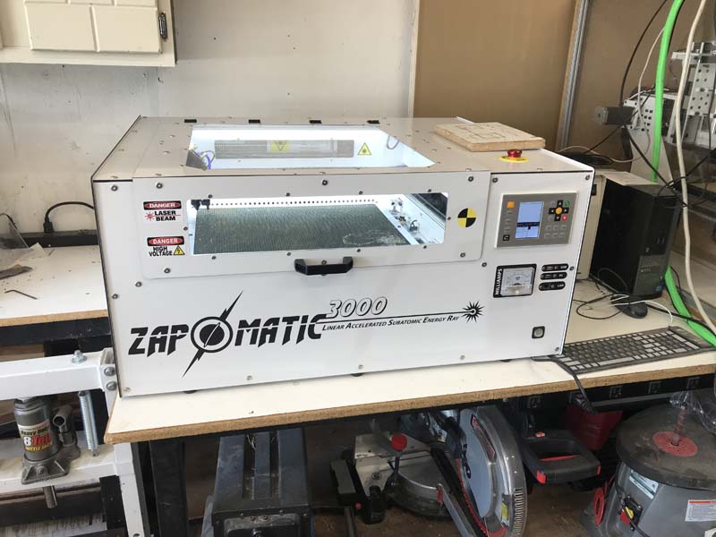
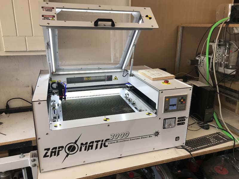
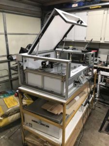
And there we have it, a finished laser engraver that works beautifully!